72 Wyniki
Wyświetl wyniki:
Sortuj według:

Podczas obliczania siły tnącej w programie Wymiarowanie betonu zbrojonego, działającą siłę tnącą Vz można zredukować zgodnie z EN 1992-1-1. Poniższy artykuł opisuje redukcję siły tnącej od obciążeń skupionych w pobliżu podpory oraz wymiarowanie sił tnących w odległości d od krawędzi podpory w przypadku obciążenia równomiernie rozłożonego.

W tym artykule pokażemy, jak zdefiniować żebra podłużne na blasze pręta za pomocą komponentu „Żebro” w rozszerzeniu Połączenia stalowe.

W tym artykule nakreślono analogię między generowaniem siatki ES dla osobnych obiektów za pomocą opcji “Preferowana niezależna siatka ES” a generowaniem siatki bez korzystania z tej opcji.

Z tego artykułu dowiesz się, jak zamodelować proste połączenie z blachą czołową w programie RFEM 6.
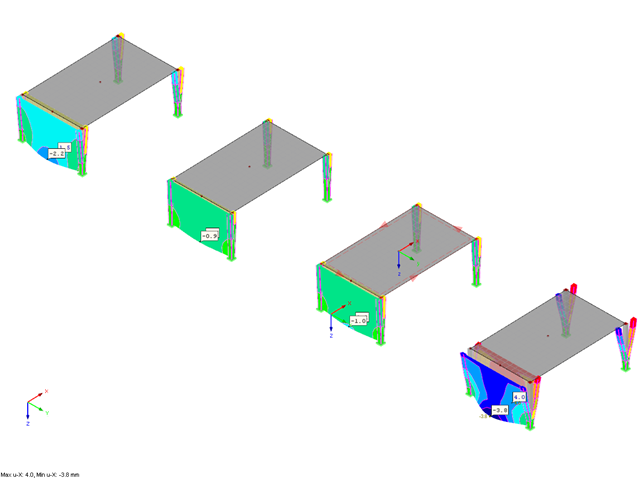
![Podstawowe kształty konstrukcji membranowych [1]](/pl/webimage/009595/2419506/01-png.png?mw=640&hash=8a9ac87bf3acfb73e6cad970f55eb968a841595c)
Niniejszy artykuł skupia się na specyficznych aspektach projektowania konstrukcji membranowych, które mają specyficzne wymagania, takich jak znajdowanie kształtu (form-finding) i generowanie szablonów cięcia. Integralną częścią projektowania tych konstrukcji jest proces wyszukiwania odpowiednich wstępnie sprężonych kształtów i generowania szablonów cięcia. Tekst krótko opisuje dwa podstawowe procesy w projektowaniu konstrukcji membranowych. Celem jest zilustrowanie ich fizycznego charakteru i zademonstrowanie poszczególnych stwierdzeń za pomocą towarzyszących im przykładów.

Zrozumienie sztywności połączeń stalowych ma kluczowe znaczenie w projektowaniu konstrukcji. Często połączenia są traktowane jako połączenia całkowicie sztywne lub przegubowe, co może prowadzić do nieekonomicznych lub nawet ryzykownych warunków projektowych. Dowiedz się, w jaki sposób program RFEM firmy Dlubal i rozszerzenie Połączenia stalowe pomagają weryfikować sztywność połączeń i nośność na zginanie, zapewniając bezpieczniejsze i bardziej ekonomiczne warunki projektowe.

W tym artykule przedstawiono model połączenia zakładkowego płatwi ZL na dachu jednospadowym, obliczony w rozszerzeniu Połączenia stalowe i porównany z tabelą nośności podaną przez producenta.
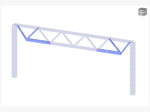
W wielu konstrukcjach szkieletowych zastosowanie prostego pręta nie jest już wystarczające. Często należy wziąć pod uwagę osłabienia przekroju lub otwory w belkach betonowych. Dla takich zastosowań dostępny jest typ pręta "Model powierzchniowy". Można go można zintegrować z modelem jak w przypadku każdego innego pręta i oferuje on wszystkie opcje modelu powierzchniowego. Ten artykuł techniczny pokazuje zastosowanie pręta typu Model powierzchniowy w istniejącym układzie konstrukcyjnym i opisuje integrację otworów pręta.
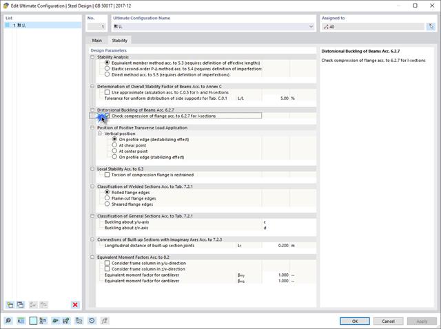
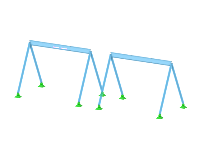
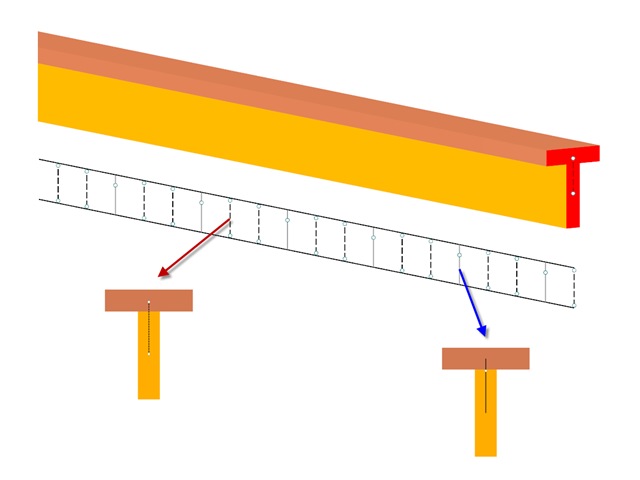
Jeżeli na górnej półce znajduje się płyta betonowa, działa ona jak podpora boczna (konstrukcja zespolona) i zapobiega problemom ze statecznością przy wyboczeniu skrętnym. Jeżeli moment zginający jest ujemny, dolna półka jest obciążona, a górna rozciągana. Jeżeli podparcie boczne nie jest wystarczające ze względu na sztywność środnika, kąt pomiędzy dolną półką a linią nacięcia środnika jest zmienny, przez co istnieje możliwość wystąpienia niestateczności wymiarowej dolnej półki.
Połączenia stalowe w programie RFEM 6 można tworzyć poprzez wprowadzenie wstępnie zdefiniowanych komponentów w rozszerzeniu Połączenia stalowe. Lista tych elementów jest stale rozszerzana, aby ułatwić modelowanie połączeń stalowych. W tym artykule przedstawiamy blachę łączącą, która została niedawno dodana do biblioteki rozszerzenia.
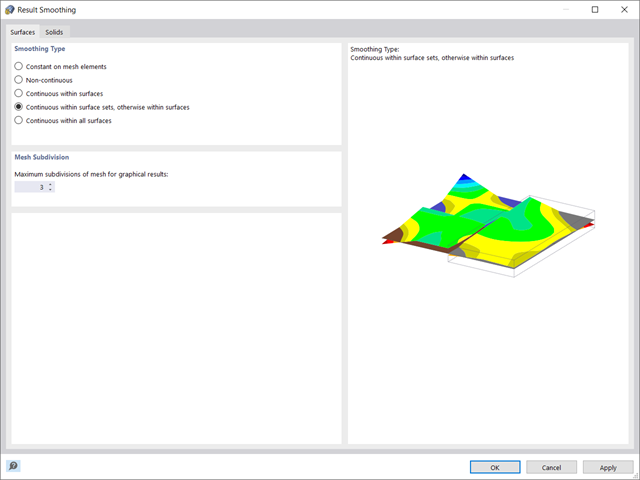
W programie RFEM 6 wyniki dla węzłów siatki ES są określane przy użyciu metody elementów skończonych. Aby rozkład sił wewnętrznych, odkształceń i naprężeń był ciągły, wartości węzłowe są uśredniane w procesie interpolacji. W tym artykule przedstawimy i porównamy różne typy uśredniania, które w tym celu można zastosować.
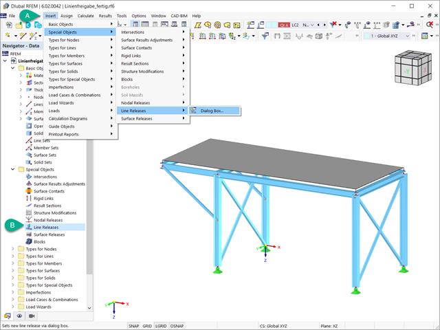
Zwolnienia liniowe to specjalne obiekty w programie RFEM 6, które umożliwiają rozdzielenie konstrukcyjne obiektów połączonych z linią. Stosowane są głównie do oddzielenia dwóch powierzchni, które nie są połączone sztywno lub przenoszą tylko siły ściskające na wspólnej linii granicznej. Poprzez definicję zwolnienia liniowego, w tym samym miejscu generowana jest nowa linia, przenosząca tylko zablokowane stopnie swobody. W niniejszym artykule przedstawiono definicję zwolnień liniowych na przykładzie praktycznym.
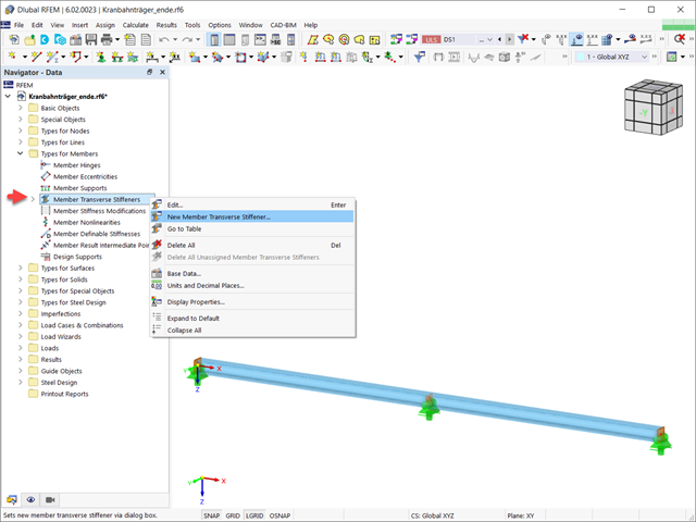
W tym artykule pokazano, jak definiować różne typy usztywnień poprzecznych pręta w programie RFEM 6 i RSTAB 9. Pokazano tu również, w jaki sposób uwzględnić je w projektowaniu i obliczeniach prętów o 7 stopniach swobody.

W programie RFEM 6 możliwe jest definiowanie spoin liniowych na liniach między powierzchniami i obliczanie naprężeń w spoinie za pomocą rozszerzenia Analiza naprężeniowo-odkształceniowa. Z tego artykułu dowiesz się, jak to zrobić.
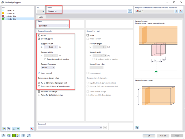
Standardowym rozwiązaniem w konstrukcji prętów drewnianych jest możliwość łączenia mniejszych prętów poprzez podparcie na większym dźwigarze. Dodatkowo warunki na końcach pręta mogą uwzględniać podobną sytuację, w której belka jest oparta na podporze. W obu przypadkach belka musi być zaprojektowana tak, aby uwzględniała nośność w poprzek włókien zgodnie z NDS 2018 s. 3.10.2 i CSA O86:19 punkty 6.5.6 i 7.5.9. W ogólnych programach do projektowania statyczno-wytrzymałościowego zazwyczaj nie jest możliwe przeprowadzenie pełnej kontroli obliczeń, ponieważ powierzchnia docisku jest nieznana. Jednak w programie RFEM 6 nowej generacji i rozszerzeniu Projektowanie konstrukcji drewnianych dodana funkcja "podpór obliczeniowych" umożliwia teraz użytkownikom uwzględnienie docisku NDS i CSA prostopadle do warunków obliczeniowych.

W tym artykule opisujemy, w jaki sposób można używać rozszerzenia Skręcanie skrępowane (7 stopni swobody) i Stateczność konstrukcji w celu uwzględnienia deplanacji przekroju jako dodatkowego stopnia swobody podczas analizy stateczności.
Zdefiniowanie odpowiedniej długości efektywnej ma kluczowe znaczenie dla uzyskania prawidłowej nośności obliczeniowej pręta. W przypadku stężeń krzyżowych, które są połączone w środku, inżynierowie często zastanawiają się, czy pręt należy rozciągnąć na całej jego długości, czy też wystarczy użyć połowy długości w miejscu połączenia prętów. W tym artykule przedstawiono zalecenia AISC i pokazano, jak określić efektywną długość stężeń krzyżowych w programie RFEM.
Efekty obciążenia śniegiem są opisane w amerykańskiej normie ASCE/SEI 7-16 oraz w Eurokodzie 1, części od 1 do 3. Normy te zostały zaimplementowane w nowym programie RFEM 6 oraz w Kreatorze obciążenia śniegiem, ułatwiającym wprowadzanie obciążeń śniegiem. Ponadto najnowsza generacja programu umożliwia zdefiniowanie lokalizacji inwestycji na mapie cyfrowej, a tym samym automatyczne zaimportowanie strefy obciążenia śniegiem. Dane te są z kolei wykorzystywane przez Kreatora obciążeń do symulacji efektów spowodowanych obciążeniem śniegiem.
Neben dem genormten Gamma-Verfahren lassen sich nachgiebig verbundene Träger auch als Stabwerksmodell abbilden.
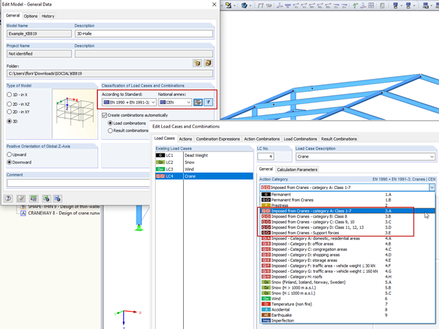
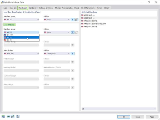
Mit Hilfe der automatischen Kombinatorik von RFEM und RSTAB und Verwendung der Option "EN 1990 + EN 1991-3; Krane" können sowohl Kranbahnträger als auch die Auflagerlasten auf die weiterführende Konstruktion bemessen werden.
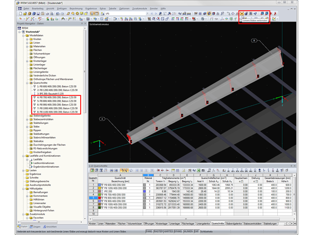
Soll in RFEM in eine bestehende Struktur nachträglich ein Voutenstab mit Zwischenknoten eingefügt werden, tritt oft die Frage auf, wie man die einzelnen Querschnittshöhen der Voutenstäbe einfach und schnell ermitteln kann. Hierfür ist die Funktion "Linien/Stäbe verbinden" sinnvoll.
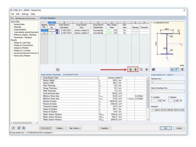
Mit RF-/STAHL EC3 ist es möglich, einen Querschnitt im Rahmen der Bemessung automatisch optimieren zu lassen. Dies erfolgt bei entsprechender Aktivierung in der Tabelle 1.3 auf Basis der aktuellen Profilreihe oder bei geschweißten Querschnitten im Rahmen der definierten variablen Parameter.
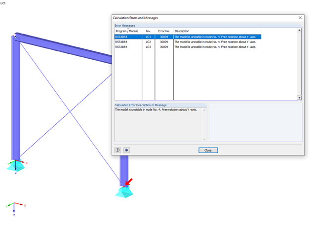
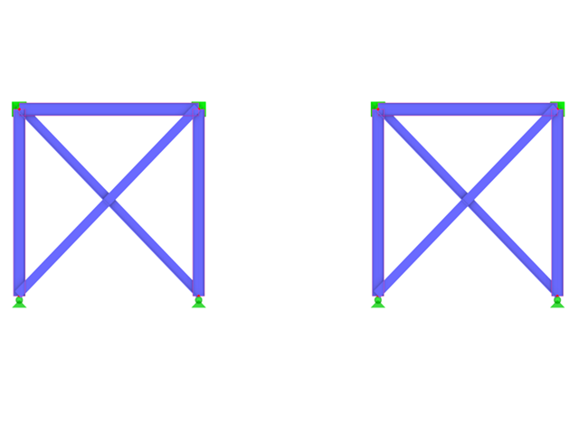
Die häufigste Ursache für instabile Modelle sind ausfallende Stabnichtlinearitäten wie Zugstäbe. Als einfachstes Beispiel dient dazu ein Rahmen, dessen Stützen am Fußpunkt gelenkig gelagert sind und am Stützenkopf Momentengelenke aufweisen. Dieses labile System soll durch einen Kreuzverband aus Zugstäben stabilisiert werden. Bei Lastkombinationen mit horizontalen Lasten bleibt dieses System stabil. Wird es jedoch ausschließlich vertikal belastet, fallen beide Zugstäbe aus und das System wird instabil, was zu einem Berechnungsabbruch führt. Dies lässt sich vermeiden, indem die besondere Behandlung der ausfallenden Stäbe unter "Berechnung" → "Berechnungsparameter" → "Globale Berechnungsparameter" aktiviert wird.
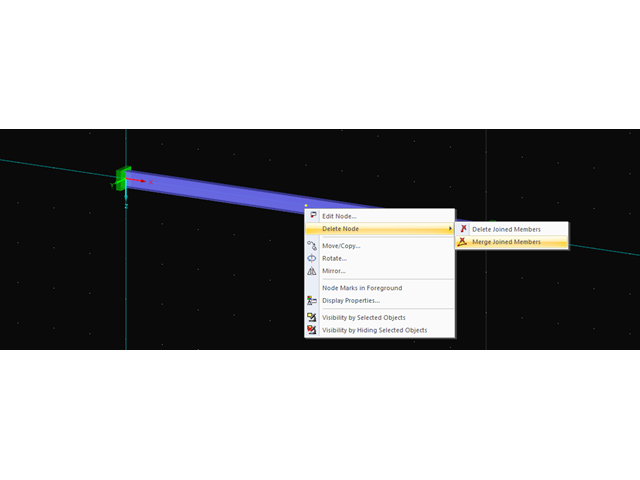
Möchte man überflüssige Knoten entfernen, anschließende Objekte jedoch erhalten, so hat man in RSTAB mit einem Rechtklick auf den betreffenden Knoten und der Option "Knoten löschen" und "Angeschlossene Stäbe verschmelzen" dazu die Möglichkeit. In RFEM können neben Stäben auch Linien miteinander verschmolzen werden.
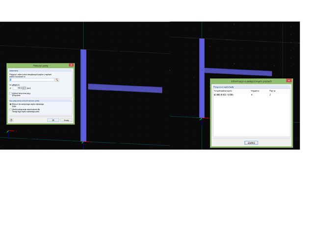
Mit der Funktion "Stäbe anschließen" können freie Stäbe an Stäbe angeschlossen werden, die in einem bestimmten maximalen Abstand liegen.
Wer nach den aktuellen Normen eine statische Berechnung für ein Tragwerk erstellen will, muss sich neben Einwirkungen und Bauteilwiderständen auch mit der Kombination der Einwirkungen befassen. Die bekanntesten Einwirkungen in der Baustatik sind zum Beispiel der ständig wirkende Lastfall Eigengewicht, die plötzlich wirkenden Lastfälle Wind und Schnee.
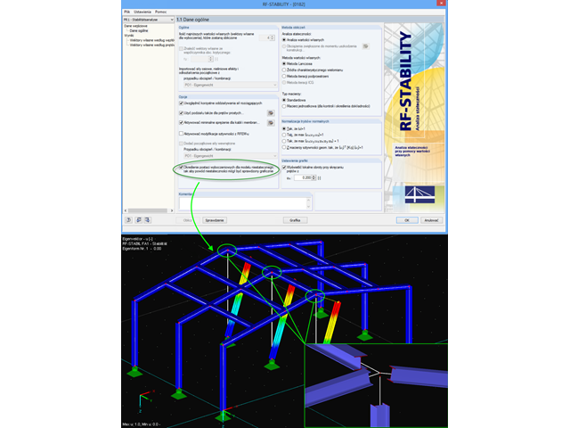
Przerwanie obliczeń spowodowane niestatecznością układu może mieć różne przyczyny. Z jednej strony może to wskazywać na "rzeczywistą" niestateczność z powodu przeciążenia układu konstrukcyjnego, z drugiej strony ten komunikat o błędzie może wynikać również z niedokładności modelowania.
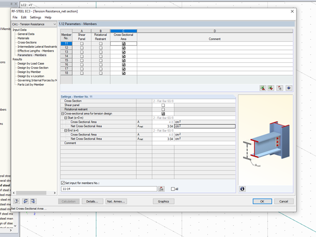
W przypadku łączenia elementów rozciąganych za pomocą połączeń śrubowych, w obliczeniach stanu granicznego nośności należy uwzględnić redukcję przekroju spowodowaną otworami na śruby. W tym artykule opisano, w jaki sposób można przeprowadzić obliczenia nośności na rozciąganie zgodnie z DIN EN 1993-1-1 przy użyciu pola przekroju netto pręta rozciąganego w module dodatkowym RF-/STEEL EC3.
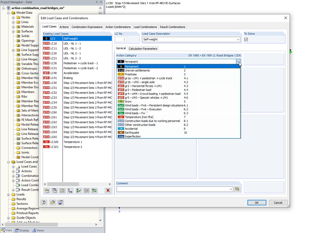
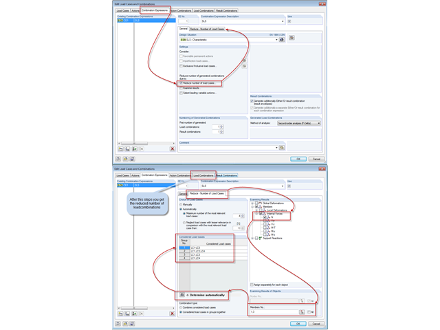
W przypadku oddziaływań na mosty drogowe oprócz podstawowych reguł kombinacji według EN 1990 należy uwzględnić także dodatkowe reguły kombinacji podane w normie EN 1991-2. W tym celu programy RFEM i RSTAB oferują automatyczną kombinatorykę, którą można aktywować w Danych ogólnych po wybraniu normy EN 1990 + EN 1991-2. Częściowe współczynniki bezpieczeństwa i współczynniki kombinacji zależne od kategorii oddziaływania są ustawiane automatycznie przy wyborze odpowiedniego załącznika krajowego.
W niniejszym artykule przedstawiono sposób symulacji podmuchu powstałego wskutek zdalnej detonacji ładunku wybuchowego. Analizę przeprowadzono w programie RF-DYNAM Pro - Forced Vibrations, a efekty porównano przy pomocy liniowej analizy przebiegu czasowego.